Monday, June 18, 2007

Under Construction: Talon 2 and Rhino II


In the smallish rockets that I build, the motor mounts have been pretty fun lately. The two main rockets that I'm working on at the moment are the Talon 2 and the Rhino II. The Rhino II is my second Rhino: the first is a cluster with 4 13mm motors; the Rhino II will fly with 5 13mm motors.


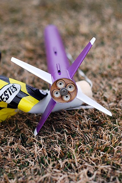
The Talon 2 my first Talon kit - it just has a 2 in the name because Giant Leap makes a bunch of different sizes of the kit. This kit is a 'high power' kit similar to the Bullet, but far more complex to build. The motor mount is shown below just before I assembled it into the rocket. The black on the one end is the motor retainer that uses snap rings rather than a screw-on cap like the retainer on the Bullet. The wire loop on the motor mount is the shock-cord mount - again, different from the U-bolt used by the Bullet.


The motor mount in the Talon 2 is 29mm in diameter and about 18" long: that's pretty big for as small a rocket as it is. It uses G-10 fins which is a new material for me to work with. G-10 is necessary for bigger, faster rockets because it is a lot stronger and less flexible than plywood. One curiousity is that it uses a nylon shock-cord with kevlar sleeve rather than a simple kevlar shock-cord - I'm not sure why that is yet.

Monday, June 04, 2007

NCR June Launch

No - I didn't launch the Bullet this weekend. It was an awesome weekend of rocketry, though.


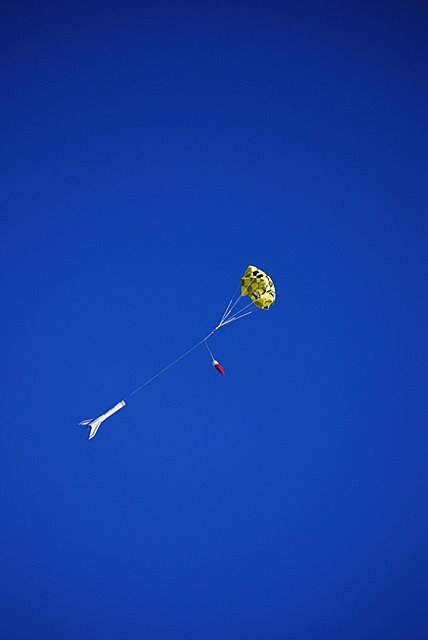
In the picture above, the two rockets were supposed to drag-race. I believe that the rules are the winner has the best 2 out of 3 of: first to altitude, highest altitude, and first to land. Art, with his BAMF, was the obvious winner in this launch because Dougs camera rocket didn't fire. The next day, they tried again and both rockets launched, but Doug's rocket was only thinking about getting to the ground first: it went up, turned over and went back down. I'm pretty sure it was super-sonic by the time it landed because it was really screaming and I was well over a mile away and could here it quite loudly. The nose cone was buried 2 feet in the hard-packed desert dirt. Art won again.

Later on the day, after dozens of other cool flights, this 14 foot long Saturn V launched. Most impressive:

Monday, May 28, 2007

Launch Log 2007.05.28

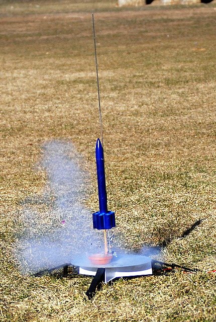
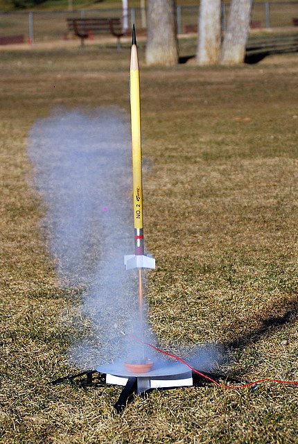
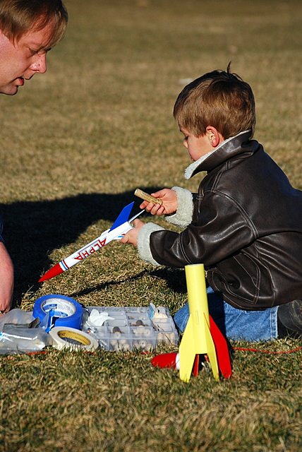
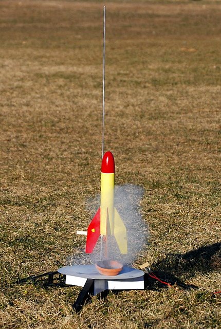
Isaac, Jeremiah, Luke, Emma, and Megan launched rockets today. We had 5 launches total with 2 of them being first flights. We need to start tracking how high the rockets go, but at this point we just see them as low, high, or really high.

The first launch was Might Mouse I with an A8-5. The Mighty Mouse is good to fly on a C, but I wanted to start with an A to introduce the girls to rockets. I think we should stick to A8-3 or just go with B or bigger in the future because the 5 second delay put the chute opening about 16 feet above ground (I was nervous).

Our second launch was the recently completed SpaceShip ONE. We used an A8-3, but that didn't work out so well. I think we'll try it again on a C, but I may not have gotten the wings straight because this launch was just kart-wheeling off the rod. We did a first flight of the UNNAMED: it flew decent and then melted the chutes on deployment. It recovered fine (fortunately, one of the chutes fully opened), but I'll have to figure out how to properly pack the chutes.

We finally launched the Alpha and the Outlaw. Both had great flights. The Alpha flew on a C6-7 and the Outlaw flew on a C6-5. Both were recovered in the same field, thanks to the calm weather. The paint on the Alpha is bubbled, so Luke and I suspect that the heat is causing it some problems. We may have to retire this one and get a new one for future flights.

Thursday, May 24, 2007

Alberto Santos-Dumont

I've not read about Alberto until now. From the little information that I have read so far in Wikipedia I suspect at least a few of the early Tom Swift books were based around this man and his achievements. I'll have to find a book about him.

It was while I was looking for information about personal blimps that I saw Alberto's name. I was reading the FAQ about the Alberto airship from SkYacht and they pointed out that they named the ship after this pioneer of aviation.

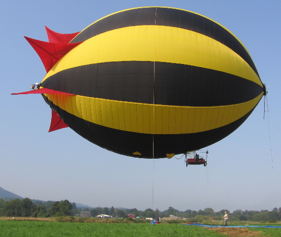
Isn't it beautiful:

Saturday, March 10, 2007

Launch Log 2007.03.10

Today was our first time launching a cluster. This one was the FlisKits Rhino with a 4-motor cluster built with centering rings from Jon's Colorado Rocketry Components.


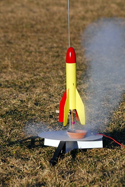
Rhino greased up with motors loadedRhino launchingRhino motors spent - a little char'd


The Rhino had two flights and both were amazing. The first flight was on 4 A3 motors and the rocket proved to flight straight. I did a quick clean-up, regreased, reloaded, and took a second flight with 4 A10's.


cleaning and reloading the Rhino

After flying the Rhino, we flew Isaac's Alpha on a C6-7... we were sure we lost the rocket because there was no sight of it even a couple minutes after the launch. While Spencer and I were over in the field to the east of the launch field, we noticed the Alpha decending over the field to the south of the launch field. Wowsers - we'll have to get a pico altimeter and beacon installed in the Alpha before another flight on a C motor!

Spencer chose the Alpha for flightAlpha lifting off - we wondered if maybe for the last time

Monday, March 05, 2007

Launch Log 2007.03.04

We had a beautiful day for a launch at the school by our house today. It was a little breezy, so we started the launch with a C6 in the Outlaw to get an idea what to expect. It was a very pretty flight because the motor was extra smoky and went nice and high.

Outlaw LaunchPipes Last LaunchPencil Last Launch


Those were the last launches of Pipes and Pencil: Pipes got tangled up in power lines and I have no idea when the power company will get it down and I doubt they'll bring it to us; Pencil was flying without a chute (because we forgot all of our chutes at home) and it turns out it doesn't do tumble-recovery so well. BTW, Pipes and Outlaw do tumble-recovery perfectly.


Shanelle went home to get chutes and then we were able to fly some more. Isaac did the prep on his Alpha rocket from Seth. The Alpha had a nice launch, but on its first flight the chute was tangled so it bounced.

Isaac installing the motor in AlphaIsaac still trying to install the motor in AlphaAlpha ready for Launch


Afer the Alpha launch, Spencer decided he was ready to launch his rocket from Seth - the Mighty Mouse. Mighty Mouse flew a couple times and as always it flew beautifully.

Mighty Mouse Ready for LaunchMighty Mouse left a nice trail and flew high on a B6


The flight was great, but got a little scary because it looked like it was coming down in a tree. It must have been just past the tree or flew through the branches.

Mighty Mouse decending nicely, but...Mighty Mouse flying just behind or through a tree


The Alpha taking a second flight - the recovery pictures are interesting because we replaced the usual rubber shock-cord with Kevlar thread. The thread is often used in contest models because it is light.

Alpha on Second LaunchAlpha recovery pictureAlpha recovery picture


Spencer did the count-down and pushed the button on 3 launches: 1 launch of the Pencil and 2 launches of the Mighty Mouse. He even recovered Mighty Mouse after its second flight.

Spencer ready to Launch Mighty Mouse for Second FlightMighty Mouse LaunchingSpencer Recovered Mighty Mouse

Saturday, March 03, 2007

March Launch Scrubbed

We went to the launch site today. The launch was 'go' as of last night, but a dozen or so of us arrived at the launch site this morning at 9a and high winds made it clear we wouldn't be launching. We waited until about 10:30a to see if the winds would die down but they didn't so the club president officially scrubbed the launch and sent the equipment trailer away :(

picture of the rockets that I took with me to the 2007.03.03 launch

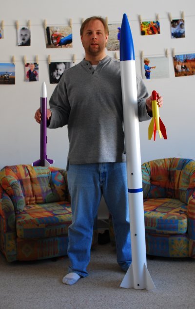
Above is a picture of the rockets that I took with me to the launch. I had expected to make my first high-power flight with the bullet today. While I didn't get to fly, I did get a chance to ask another club member to look over the rocket. The red and yellow is an Estes Baby Bertha kit that we've named Mighty Mouse - I actually took two of those today: one with a since 18mm motor mount and one with a cluster of 3x13mm motor.

Tuesday, January 30, 2007

The Astronaut Farmer

I first heard about the Astronaut Farmer while looking at the CP Technologies Web site (my quest for ideas on small-scale strap-on booster designs). There was a lot of information there about the movie and skimming the info, I decided that I'd like to go to the movies on Feb 23 (opening night). It worked out that I was able to go a screening of the show today - great movie, in my opinion.

There was a point in the movie where there is a failure and I was horrified: I thought that the BATFE had worked with the Polish Brothers to help the public see the 'light' on their current case affecting rocket propellant and ignitors used by hobbyists. In the movie, it is the FBI rather than the BATFE, but a similar idea (Farmer was fine building his rocket - it was when he attempted to buy fuel that he got into trouble - even though he had attempted to follow known regulations).

There is a lot of family focus in the movie - the kind that I like because it helps me consider my role as a parent and gives me some things to think over. Some details are ignored - again, a nice thing - for example, Farmer allows the public to come into his garage and see the rocket and the line goes on for miles (apparently, these were only the most well behaved humans on the planet because there was no mess and no fights). I believe that the movie was filmed in New Mexico - I only mention it because the house, the ranch, etc. were so pretty that they really complimented the story / experience.

Good stuff.

Monday, January 29, 2007

Feb launch scrubbed but...

I'm not too down: on Monday, January 29th, I'll be attending a screening of The Astronaut Farmer and when we do get to launch, I'll be attempting my L1 cert on my second flight of the Bullet. I've been assisting with some PHP on the club Web site and one of the members showed me the casing and motor I'll be using for my L1 :) I'll have to pay for the H73 motor, but I'll be able to borrow the casing.

Friday, January 19, 2007

building a few cluster models

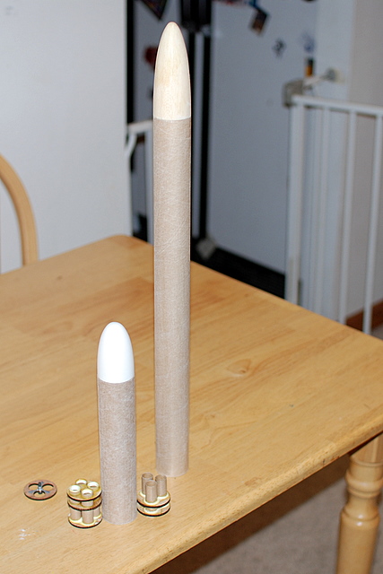
We have a rocket day coming in the next month or two at church, so I'm building a couple models size rockets for launching there. These are my first venture into clusters - and they are tiny clusters. The tall rocket is a Rhino and the shorter one is a Baby Bertha.
the Baby Bertha and Rhino with their cluster motor mounts
Both rockets use BT-60 size tubes, so I picked up a couple cluster mounts from a local rocket guy. The Baby Bertha will use 3 tiny A motors and the Rhino will use 4; this will give the Baby Bertha about 6.6 N-s and the Rhino 8.8 N-s of total impulse (equivalent of mid-C).

Wednesday, January 03, 2007

Jan 6 launch scrubbed

Disappointing :(

Regrettably but sensibly, NCR will NOT attempt to launch on Saturday the 6th. Our equipment trailer remains buried in deep snowdrifts and is pretty much in-accessible, as is the Atlas Site.
- from http://www.ncrocketry.org/

Tuesday, December 26, 2006

preparing for first Bullet flight

Still have some finishing work to do on the Bullet, but it is nearly ready for its first flight. I'm planning on flying a couple flights on Jan 6 at the Northern Colorado Rocketry launch.
Isaac next to the Bullet with avionics bay and extension installed

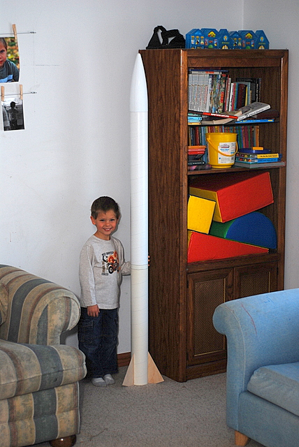
In this picture, the base kit has had an avionics bay and an extension added. The avionics bay will carry the electonics that Michael and I have been working on. The extension is simply there to connect the avionics to the nose cone, but the additional length helps the rocket fly stably with heavy tail.

One last bit (besides the finishing of the rocket) is to test fire a motor. I'll be using a reloadable motor system and I need to verify that I can safely assemble and fire the engines without it blowing up or failing to fire the ejection :)

Thursday, December 21, 2006

some individuals weights

I've been wondering how much my quick links weigh and other individual parts. I finally got around to weighing the stuff this evening:

  • 1200 lbs quick link - almost exactly 1 oz

  • 800 lbs quick link - about 1/2 oz

  • 660 lbs quick link - about 1/3 oz

  • 16 ft kevlar - about 3/4 oz


It's kinda funny that I differentiate between 1/2 and 1/3 because my scale isn't that precise, but that's the way I read it.

Saturday, December 16, 2006

device direction

We're trying to make a decision on the device that we want to commit to. We've been bouncing between the PIC and the AVR for a while and feel that we need to pick one to focus on. In my initial research, it seems like the AVR and PIC are pretty much equivalent competing products. I have seen some vague references (i.e. both device families have similar features as well as unique features so the process of choosing one can be daunting) to differences in the families, but nothing helpful or specific yet.
Michael has gathered some great links. We'll likely consider where we want to be in the longer term (guidance) and see if one of the product families fit better than the other.

Wednesday, December 13, 2006

testing R/C with an igniter

I hooked everything up expecting to be disappointed. I thought that it was all good in theory, but it surely wouldn't work in practice. Making a hot fire would surely be more difficult that turning on an LED.
first attempt at using the R/C circuit with a real igniter

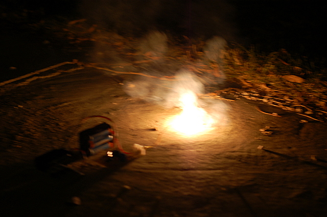
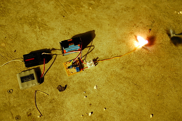
In the first attempt, I took the pictures and I am all sorts of no good at taking pictures. Shanelle assisted in the second attempt by taking some excellent pictures. I hooked everything up and told Shanelle what to expect and then flipped the switch.
the igniter is smoking just before firingthe igniter fires nice a brightigniter cooling down after firing


It takes about 3 seconds for the igniter to get hot enough to fire. I'm just using a 6 cell AA pack of NiMH batteries. The total voltage is 8.4 volts - quite a bit lower than the preferred 12 volts. It's nice that the igniters were willing to give me joy on the 8.4.

Tuesday, December 12, 2006

another post about the R/C backup circuit

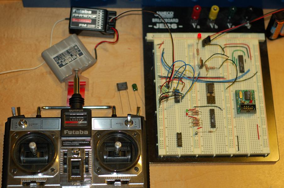
I tested the R/C circuit with a few different types of capacitors and 4013s. Actually, the 4013 that I had been using was SGS and tonight I tested with a Motorola one. Of course, one expects them to work the same, but I needed to try it to make sure. The yellow capacitor that is in the circuit is one that I picked up last week: a fancy poly cap that isn't truely a precision capacitor, but it is rated at +/- 1%. The black boxy one sitting next to the bread board is +/- 10%. The green one is the one I have been using and is also +/- 10%.
r/c circuit with various capacitors - LED offr/c circuit with various capacitors - LED on


The difference between the two images above is the position of the gimble. Turning the LED on when using the 1% capacitor takes 1 click at the center of the throw. When I use the black box capacitor, it takes 2 clicks about 2/3 up in the throw. When using the green capacitor, it takes 2 clicks at the center. After 1 click from off, the lower precision capacitors flicker. Of course, in real action, I'll use the switch (top left of the controller), but the gimble adjustment seems like a good test to see where the circuit is sensitive.

I feel good about the reliability of the circuit and parts availability, so it is time to solder a version together and test the first circuit with some higher current. The yellow capacitors are expensive at 30 cents each, but not prohibitively expensive - I think that I'll start with those and I'll use the Motorola 4013 since I have more of those than the SGS. The firing mechanism is currently using an IRF 531, which are locally available, so I'll be putting that into the initial prototype.
first soldered prototype of the r/c circuit

Saturday, December 09, 2006

all power

This car is all power. In fact, before Isaac installed the house, he decided it was too much power for his lego man. He installed a man with a helmet and we had to brainstorm to come up with a seat belt before taking any more drives!
picture of Isaacs car with a seat belt installed
Note that this was taken with the boys' camera... it isn't a Canon / Nikon thing.

Thursday, December 07, 2006

XM Radio Constellation

I was curious to find out how big the XM Radio constellation is because I was so impressed with our reception on our Thanksgiving trip to the mountains. On our way back from the cabin we rented, we took some roads that were in between mountains and deep in the trees and we never lost reception.

Well, the XM Radio wikipedia entry has lots of great info, but it wasn't immediately obvious how big their constellation is or current orbits. While searching around, I bumped into the decode systems page which led me to VITA.

I know nothing about VITA - perhaps they are scum; however, the interesting bit to me is that there is a group of volunteers that have a license for a satellite constellation. Interesting. Serendipity do day.

great capacitor resources

I'm struggling to grok all that capacitors are and do. Here are a couple resources that I assume that I'll keep coming back to. Capacitor Concepts has a nice graph about types of capacitors, what they are used for, and related equations for the different types and uses. This site details the meanings of various capacitor markings - important for me because I have accumulated a bunch of capacitors and very few say helpful things like 10uF 50VDC; most of my capacitors say things like 0.1k or 103M.

R/C Backup Recovery

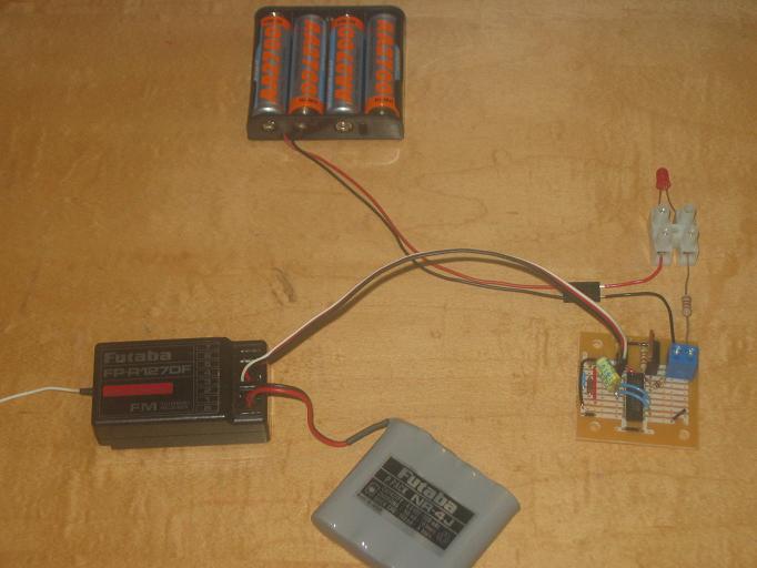
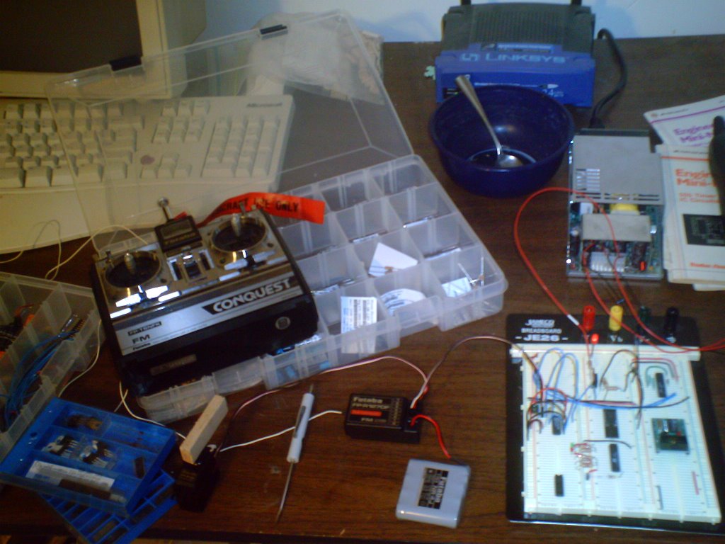
This great (old) article by Ron Hewitt shows a simple circuit to capture an R/C signal. I built the circuit as-is with parts that I happened to have and the Michael and I modified it to fit recovery needs.
picture of the R/C circuit in action

I attempted to build this similar circuit, but didn't have all the parts necessary. I got some variance where the transistor would be when I moved the gimble, but I wasn't able to complete the circuit to drive a MOSFET or anything. I like the 4013 circuit because it worked first time and is now my circuit.

This excellent page gave us a lot of good information about the way the receiver is communicating with the servos. I would have liked to build the circuit they use, but the local electronics store was out of both the 74HC123 and 74HC74! It isn't worth $5 in shipping to get $1.28 in parts, so I think I'll put off building this one until some other time.

Monday, December 04, 2006

nanotubes to diamonds

I always knew that diamonds were carbon, graphite was carbon, etc. but I have never heard it put this way:
Diamonds are three-dimensional crystals of pure carbon. Two-dimensional carbon is graphite, while nanotubes are considered a one-dimensional form of pure carbon. (Technically, graphite and nanotubes have three dimensions, but the Z axis on graphite and the Z,Y axes on nanotubes are so small that they become irrelevant.)
- from a news.com article

Saturday, December 02, 2006

my first SMD solder attempt

I had intended to use the toaster oven or electric skillet for doing surface mount, but I found out today that the required solder paste is hard to get and mighty expensive. I had to revert to doing it by hand.
setting things out in preparation to solder the PIC

My strategy was to tack the chip down on pins 1 and 18. That turned out to be more difficult than I had anticipated: when I'd get the solder soft to move the chip for alignment, I'd repeatedly move it too far. I finally got it aligned and then soldered all pins in a rough fashion - just making sure I got a good bead on each lead and it flowed under the PIC leads. After everything had some solder on it, I used a fine desolder braid briefly on each lead to pull up the bridges.
image of the PIC and adaptor connected to bread-board

After everything was soldered, I tested by poking each pin to see if it moved. None did. Then I put the PIC / adaptr into the bread-board to check resistance. I had an initial scare when I hit Vcc, but then I realized that would probably be okay. I'm looking forward to trying out a circuit now.

Thursday, November 30, 2006

learning about MOSFETS and gain

Crocodile Clips only has two configurable parameters for a n-channel MOSFET: the gain factor and the threshold voltage. Since the other voltages (i.e. drain-source, gate-source, etc.) and parameters are not configurable for the sake of simulations, I'll guess that the voltage and current specs are limits for the sake of breakdown and focus on gain and threshold until I learn more. None of the data sheets that I have looked at speak of a 'gain factor', but I read that forward transconductance what Croc Clips means by gain factor.
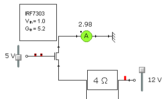
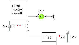
simple circuit using IRF7101 specssimple circuit using IRF7303 specssimple circuit using IRF531 specs

In the pictures above, I have changed the MOSFET parameters in Croc Clips to use the threshold voltage and gain factor from the data sheets for the IRF7101, IRF7303, and IRF531. The IRF7101 is used in the Roctronics circuits, so I'm using that as a baseline in the simulations. The IRF7303 is more readily available now, so we're considering it in our schematics for our implementation of the Roctronics boards. The IRF531 is available locally and in the nice TO-220 package that make bread-boarding easy. In short, it appears that our requirements are basic enough that we can use any of the MOSFETs we are looking at.

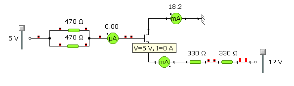
In my previous post, I wonder about the resistance from gate to source... heh, I now have a better understanding of the 'field-effect' part of MOSFET (and I already know that the MOS part is obsolete). There is 'practically no input current' on the gate - you can see in this simulation that Croc Clips assumes none:
picture of my original circuit that had the unnecessary resistors

So for the most part, when we pass the voltage threshold on the gate, the MOSFET turns on. Below are some rules that I picked up on a Web site talking about the scaling effects of MOSFETs - I may have interpretted the gain part of the equations incorrectly. Even if these aren't completely accurate - they appear to be pretty decent guides based on my playing with the Crocodile Clips.

drain-source current:
cutoff: 0 when Vg < Vt (i.e. 3.8 < 4)
linear: GainFactor * ((Vg - Vt) Vd - (Vd^2 / 2)) when 0 < Vd < Vg - Vt
saturation: (GainFactor / 2) * (Vg - Vt)^2 when 0 < Vg - Vt < Vd

oops ... pop :( learning about MOSFETs

In books, the descriptions of MOSFETs are so simple; look at a MOSFET data sheet and it isn't quite so simple. The most big question in my mind is the drain current min - why is there a min. Does that mean that the MOSFET can support at least that specific current?

The IRF531 looked nice, so I bought a couple to learn with. I'm have a pretty basic multimeter and a limited set of resistors, so I bread-boarded some circuits with the intent of getting a most basic understanding. Here are my notes in preparation for bread-boarding and testing:

Specific Constraints
- 0-25 mA and 0-250 mA test ranges on multimeter
- 330 ohm and 470 ohm resistors are only small resistors available
- both types of small resistors are 1/2 watt resistors

Playing with MOSFET
- assuming no resistance at all on gate-source
- circuit: +5 ... 235ohm ... gate-source ... Gnd
- 21 mA used
- if resistance on gate-source, then current used will be smaller
- assuming negligable resistance (< 1ohm) on drain-source
- circuit: +12 ... 660ohm ... drain-source ... Gnd
- 18 mA used
- if 5V @ 20 mA isn't enough to turn MOSFET on, then current will be smaller


You know what's coming - after careful consideration of my constraints and building my circuit, I blew the fuse in my multimeter! I have no spares, so I'll have to finish testing tomorrow :( My mistake, besides doing this in real life rather than with Crocodile Clips, was that I didn't plan my volt versus amp metering locations. Live and learn - at least I lived...

3D representation of the MOSFET test using Croc Clips

Now that is the smart way to learn! The 3D view is pretty and neato, but what I'm not showing is the schematic with ammeter and voltmeters installed. Good stuff!

Tuesday, November 28, 2006

talking to the uMMC

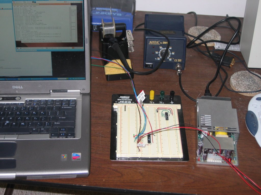
I hooked up the uMMC to the PC tonight. I couldn't find an MMC or SD card around, so I just had to verify the connection and query the status of the system.
picture of the uMMC breadboarded and connected to a PC
The first command I used was Z which queries the system status - the return was error code E08: Card not inserted; the other command I typed was V to request the system version and serial number - the return is kinda funny: VVV.MM SN:UMM1-NNNN-NNNN is expected, but I got 101.56 SN:UMM1-OEM - I have no serial number...

Ah well - nice to have something work. In the breadboard, I have the Vcc and Gnd on the uMMC going directly to the 5V from my power supply; the G, T, and R on the uMMC connect to the TTL Gnd, TTL Tin, and TTL Rout on the MAX232 (Sipex in this case); finally, the PC Serial has Gnd (5), Tx (3), and Rx (2) connected to the Gnd, RS-232 Rin, and RS-232 Tout. The PC serial uses 8N1 w/ no flow control @ 9600 as the default.

Monday, November 27, 2006

communication with AVR established!

By a bizzare turn, I happened to get communication with the AVR established - I have uploaded my program! :) Funny how things happen - I had given up on getting the AVR programmed via the parallel port and was going to try a serial method that Michael had found; I was closing out tabs in my browser and one happened to be pointing at this post about disabling the parallel port on the VMWare site. It made me suspect that my parallel port in my VM was not set for bidirectional communication, so I manually edited my VMX file to add 3 lines... and it worked!

parallel0.present = "TRUE"
parallel0.fileName = "LPT1"
parallel0.bidirectional = "TRUE"


Assuming the same old error as before, I ran uisp and got a nice little surprise!

uisp -dlpt=/dev/parport0 --erase -dprog=dapa
Atmel AVR ATtiny2313 is found.
Erasing device ...
Reinitializing device
Atmel AVR ATtiny2313 is found.
uisp -dlpt=/dev/parport0 --upload if=avrledtest.hex -dno-poll -dprog=dapa -v=3 --hash=32
Reset inactive time (t_reset) 1000 us
AVR Direct Parallel Access succeeded after 0 retries.
Vendor Code: 0x1e
Part Family: 0x91
Part Number: 0x0a
Atmel AVR ATtiny2313 is found.
Page Write Disabled
FLASH Write Delay (t_wd_flash): 11111 us
EEPROM Write Delay (t_wd_eeprom): 11111 us
Uploading: flash
#####
(total 138 bytes transferred in 1.71 s (81 bytes/s)
Now - if only my code worked right :) But that is my own bug and I can fix that!

One other great thing that I learned in this experience is that the Add / Remove Programs wizard (in Ubuntu) has an Advanced tab that allows you to select specific packages. Michael pointed out the Advanced tab and that uisp is in the package list! Good stuff.

Tuesday, November 21, 2006

mission failure - how to load AVR

I had the simple task of loading my program onto the AVR tonight to see it execute my own code for the first time; I should have suspected there was no hope. The task was too simple.
sad picture of breadboarded AVR waiting for a program to run
I found that I didn't have uisp loaded on Ubuntu already - no worries, I thought. I'll just build it... './configure --prefix=/usr/local/avr'. Boom - g++ not available on the Ubuntu install that I'm using. I checked the Applications - Add / Remove and I don't see it, but it must be added through some other process. So I resorted to my backup plan - install avrdude. No joy there, either: don't have yacc installed.

Back in the day when the whole system was compiled and you knew what was on it, installing g++ or yacc was a no-brainer. It is probably still a no-brainer, but ... all I want to do is load my program onto the AVR - why am I installing a new compiler or compiler compiler?! *sigh* Tired from Linux rot.

Saturday, November 18, 2006

no need to build boards!

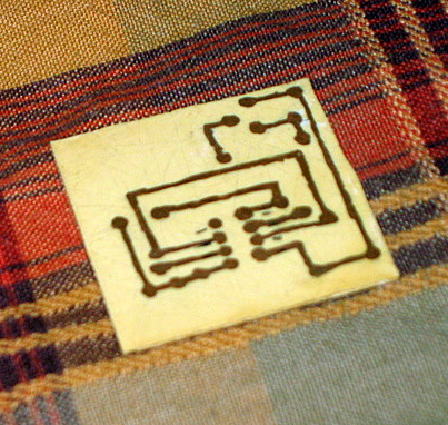
picture of the last board that I madeThis is the last board that I etched myself - I don't enjoy the process at all. Michael found BatchPCB and we get etching, solder mask, silk screen, and the holes drilled! Woohoo! We haven't tried the service yet, but probably soon.

Thursday, November 16, 2006

large capacitors

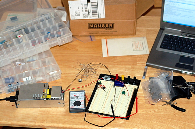
We have read that 3300+ uF capacitors could be the key to reliable ejections, so here I am playing with a 4700 uF capacitor running through 430ohms for draining it to see what kind of current I get. Good stuff!

breadboarding with large caps

After that goodness, I cleared the board and build the Roctronics AVR Controller (minus the MOSFETS and EEPROM) and RS232 Interface. I found that Jameco substituted a Sipex chip for the Maxim MAX233 that I had ordered; no problem there, just figure I should link to the correct data sheet.
Friday, November 10, 2006

spicy ubuntu

Until today, my main reason for liking Ubuntu was that is was a simple multi-user system without a root / administrator account to set up. After an unsuccessful attempt to build SPICE, I looked on the forums and learned about the various repositories for Ubuntu programs. Hitting the repositories is easy - I just hadn't ever tried the Ubuntu Add / Remove Programs before :)

So here's a nice resource that I bumped into on the forums: Ubuntu Scientists It shows projects like Oregano and gEDA and what repository they are in. Good stuff.

Thursday, November 09, 2006

preparing to build rocket electronics

The Roctronics projects was active a couple years ago, but there isn't anything completely buildable there at the moment. Michael is redesigning the harness and controller boards with available parts so that we can move forward with a first implementation.

For my own reference, this is a list of parts that I have ordered and the data sheets:
39357-0002 - Eurostyle Terminal Block (for connecting power and ejection charges)
PIC16F628-20/SO - PIC Microcontroller
ATtiny2313 - AVR Microcontroller
254-PB521 - 100dB Buzzer (to mount in electronics bay of rocket for locating)
BZX79C5V6 - 5.6V Zener Diode
SN74LS00N - standard logic IC
SN74LS04N - standard logic IC
SN74LS07N - standard logic IC
SN74LS90N - standard logic IC
CD40110BE - standard logic IC
L7805ABV - 5.0V 1.0A positive voltage regulator
L7812ACV - 12V 1.0A positive voltage regulator
MAX233CPP - RS232 driver / receiver
PN2907A - standard PNP transitor

A beautiful thing about electronics is that most of the parts are in the $0.10 range, so I could order a bunch and deal with mistakes :)

first use of wikibooks

Most people are already familiar with the Wikipedia and may already be familiar with Wikibooks; however, I just ran into Wikibooks for the first time. Impressive stuff, in my opinion.

I was having a hard time finding a MAX233 chip required by a circuit, but I kept seeing a MAX232A and MAX233CPP. A Google search led me to this great serial programming book. Good stuff.

Wednesday, November 01, 2006

Ready for Recovery

The LOC/Precision Bullet came with a 12' elastic bungie cord for use as the recovery harness. Based on my reading in Modern High-Power Rocketry 2, I decided to replace the recovery harness. I already built in a U-bolt on the forward centering ring in the motor mount, so I can anchor to that rather than use the LOC SCM 1 harness mount. I picked up 3 quick-links from Home Depot and 16' of Kevlar shock cord.

The main problems with the elastic bungie are that it won't last like Kevlar since it lives in the booster airframe (because of ejection charges), it can break easily, and it is elastic and may cause the ejected nose cone to bounce back into the booster and do damage. The main risk with Kevlar is that it could result in zippers if the ejection wasn't timed well or if the shock cord was too short.

I expect to plan my flights using wRASP and RockSim, so I hope to get my timings set good enough to prevent serious damage. In addition, using the 16' of shock cord falls in the guideline of making the shock cord at least 2 to 3 times the length of the rocket so the bodies have some time to slow down before the cord gets pulled.

So anyway - the reason for this post was so I could write down somewhere the weights of the recovery harness. The chute, quick links, and shock cord weight a total of 6.7 ounces. The chute is still the original 36" rip-stop nylon.