
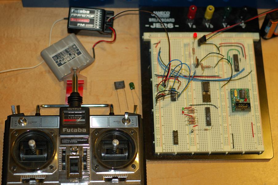
The difference between the two images above is the position of the gimble. Turning the LED on when using the 1% capacitor takes 1 click at the center of the throw. When I use the black box capacitor, it takes 2 clicks about 2/3 up in the throw. When using the green capacitor, it takes 2 clicks at the center. After 1 click from off, the lower precision capacitors flicker. Of course, in real action, I'll use the switch (top left of the controller), but the gimble adjustment seems like a good test to see where the circuit is sensitive.
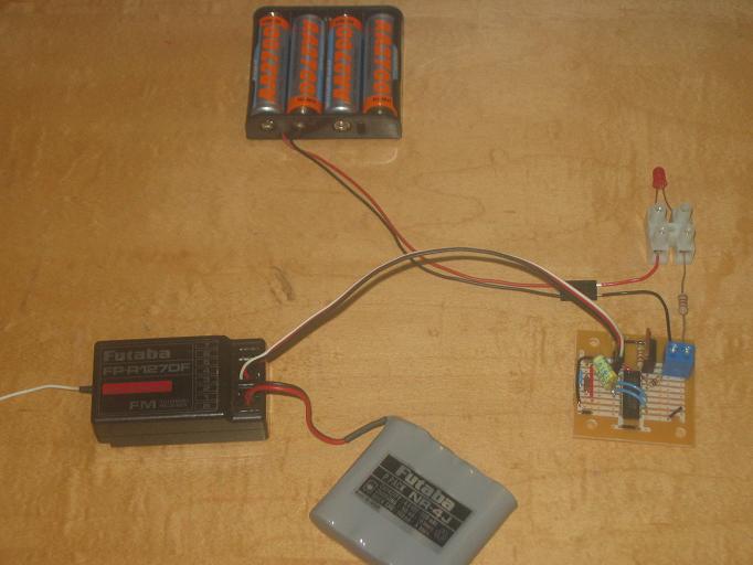
I feel good about the reliability of the circuit and parts availability, so it is time to solder a version together and test the first circuit with some higher current. The yellow capacitors are expensive at 30 cents each, but not prohibitively expensive - I think that I'll start with those and I'll use the Motorola 4013 since I have more of those than the SGS. The firing mechanism is currently using an IRF 531, which are locally available, so I'll be putting that into the initial prototype.
No comments:
Post a Comment