Tuesday, December 26, 2006

preparing for first Bullet flight

Still have some finishing work to do on the Bullet, but it is nearly ready for its first flight. I'm planning on flying a couple flights on Jan 6 at the Northern Colorado Rocketry launch.
Isaac next to the Bullet with avionics bay and extension installed

In this picture, the base kit has had an avionics bay and an extension added. The avionics bay will carry the electonics that Michael and I have been working on. The extension is simply there to connect the avionics to the nose cone, but the additional length helps the rocket fly stably with heavy tail.

One last bit (besides the finishing of the rocket) is to test fire a motor. I'll be using a reloadable motor system and I need to verify that I can safely assemble and fire the engines without it blowing up or failing to fire the ejection :)

Thursday, December 21, 2006

some individuals weights

I've been wondering how much my quick links weigh and other individual parts. I finally got around to weighing the stuff this evening:

  • 1200 lbs quick link - almost exactly 1 oz

  • 800 lbs quick link - about 1/2 oz

  • 660 lbs quick link - about 1/3 oz

  • 16 ft kevlar - about 3/4 oz


It's kinda funny that I differentiate between 1/2 and 1/3 because my scale isn't that precise, but that's the way I read it.

Saturday, December 16, 2006

device direction

We're trying to make a decision on the device that we want to commit to. We've been bouncing between the PIC and the AVR for a while and feel that we need to pick one to focus on. In my initial research, it seems like the AVR and PIC are pretty much equivalent competing products. I have seen some vague references (i.e. both device families have similar features as well as unique features so the process of choosing one can be daunting) to differences in the families, but nothing helpful or specific yet.

Michael has gathered some great links. We'll likely consider where we want to be in the longer term (guidance) and see if one of the product families fit better than the other.

Wednesday, December 13, 2006

testing R/C with an igniter

I hooked everything up expecting to be disappointed. I thought that it was all good in theory, but it surely wouldn't work in practice. Making a hot fire would surely be more difficult that turning on an LED.
first attempt at using the R/C circuit with a real igniter

In the first attempt, I took the pictures and I am all sorts of no good at taking pictures. Shanelle assisted in the second attempt by taking some excellent pictures. I hooked everything up and told Shanelle what to expect and then flipped the switch.
the igniter is smoking just before firingthe igniter fires nice a brightigniter cooling down after firing


It takes about 3 seconds for the igniter to get hot enough to fire. I'm just using a 6 cell AA pack of NiMH batteries. The total voltage is 8.4 volts - quite a bit lower than the preferred 12 volts. It's nice that the igniters were willing to give me joy on the 8.4.

Tuesday, December 12, 2006

another post about the R/C backup circuit

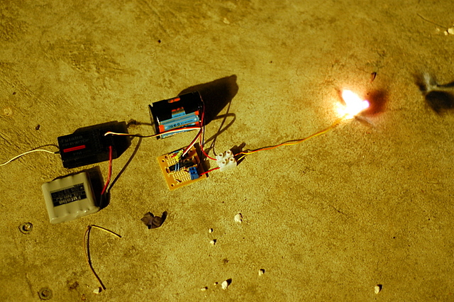
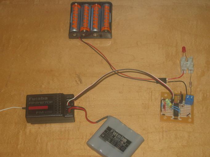
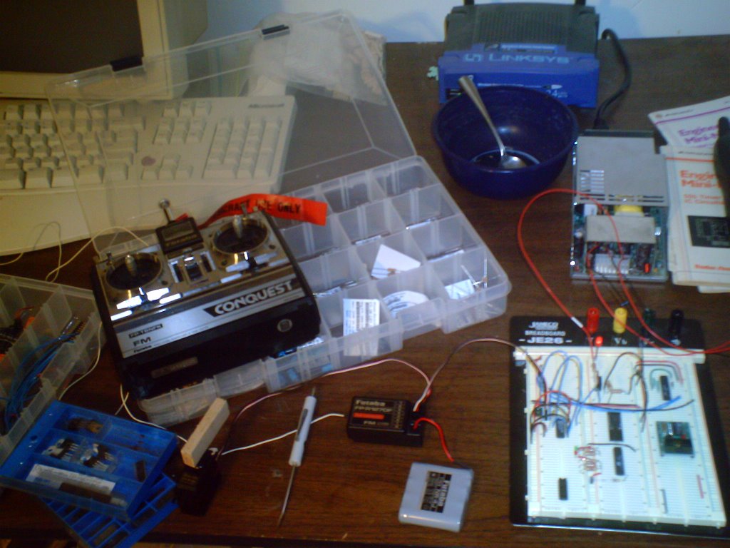
I tested the R/C circuit with a few different types of capacitors and 4013s. Actually, the 4013 that I had been using was SGS and tonight I tested with a Motorola one. Of course, one expects them to work the same, but I needed to try it to make sure. The yellow capacitor that is in the circuit is one that I picked up last week: a fancy poly cap that isn't truely a precision capacitor, but it is rated at +/- 1%. The black boxy one sitting next to the bread board is +/- 10%. The green one is the one I have been using and is also +/- 10%.
r/c circuit with various capacitors - LED offr/c circuit with various capacitors - LED on


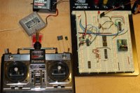
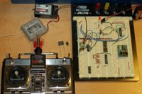
The difference between the two images above is the position of the gimble. Turning the LED on when using the 1% capacitor takes 1 click at the center of the throw. When I use the black box capacitor, it takes 2 clicks about 2/3 up in the throw. When using the green capacitor, it takes 2 clicks at the center. After 1 click from off, the lower precision capacitors flicker. Of course, in real action, I'll use the switch (top left of the controller), but the gimble adjustment seems like a good test to see where the circuit is sensitive.

I feel good about the reliability of the circuit and parts availability, so it is time to solder a version together and test the first circuit with some higher current. The yellow capacitors are expensive at 30 cents each, but not prohibitively expensive - I think that I'll start with those and I'll use the Motorola 4013 since I have more of those than the SGS. The firing mechanism is currently using an IRF 531, which are locally available, so I'll be putting that into the initial prototype.
first soldered prototype of the r/c circuit

Saturday, December 09, 2006

all power

This car is all power. In fact, before Isaac installed the house, he decided it was too much power for his lego man. He installed a man with a helmet and we had to brainstorm to come up with a seat belt before taking any more drives!
picture of Isaacs car with a seat belt installed
Note that this was taken with the boys' camera... it isn't a Canon / Nikon thing.

Thursday, December 07, 2006

XM Radio Constellation

I was curious to find out how big the XM Radio constellation is because I was so impressed with our reception on our Thanksgiving trip to the mountains. On our way back from the cabin we rented, we took some roads that were in between mountains and deep in the trees and we never lost reception.

Well, the XM Radio wikipedia entry has lots of great info, but it wasn't immediately obvious how big their constellation is or current orbits. While searching around, I bumped into the decode systems page which led me to VITA.

I know nothing about VITA - perhaps they are scum; however, the interesting bit to me is that there is a group of volunteers that have a license for a satellite constellation. Interesting. Serendipity do day.

great capacitor resources

I'm struggling to grok all that capacitors are and do. Here are a couple resources that I assume that I'll keep coming back to. Capacitor Concepts has a nice graph about types of capacitors, what they are used for, and related equations for the different types and uses. This site details the meanings of various capacitor markings - important for me because I have accumulated a bunch of capacitors and very few say helpful things like 10uF 50VDC; most of my capacitors say things like 0.1k or 103M.

R/C Backup Recovery

This great (old) article by Ron Hewitt shows a simple circuit to capture an R/C signal. I built the circuit as-is with parts that I happened to have and the Michael and I modified it to fit recovery needs.
picture of the R/C circuit in action

I attempted to build this similar circuit, but didn't have all the parts necessary. I got some variance where the transistor would be when I moved the gimble, but I wasn't able to complete the circuit to drive a MOSFET or anything. I like the 4013 circuit because it worked first time and is now my circuit.

This excellent page gave us a lot of good information about the way the receiver is communicating with the servos. I would have liked to build the circuit they use, but the local electronics store was out of both the 74HC123 and 74HC74! It isn't worth $5 in shipping to get $1.28 in parts, so I think I'll put off building this one until some other time.

Monday, December 04, 2006

nanotubes to diamonds

I always knew that diamonds were carbon, graphite was carbon, etc. but I have never heard it put this way:
Diamonds are three-dimensional crystals of pure carbon. Two-dimensional carbon is graphite, while nanotubes are considered a one-dimensional form of pure carbon. (Technically, graphite and nanotubes have three dimensions, but the Z axis on graphite and the Z,Y axes on nanotubes are so small that they become irrelevant.)
- from a news.com article

Saturday, December 02, 2006

my first SMD solder attempt

I had intended to use the toaster oven or electric skillet for doing surface mount, but I found out today that the required solder paste is hard to get and mighty expensive. I had to revert to doing it by hand.
setting things out in preparation to solder the PIC

My strategy was to tack the chip down on pins 1 and 18. That turned out to be more difficult than I had anticipated: when I'd get the solder soft to move the chip for alignment, I'd repeatedly move it too far. I finally got it aligned and then soldered all pins in a rough fashion - just making sure I got a good bead on each lead and it flowed under the PIC leads. After everything had some solder on it, I used a fine desolder braid briefly on each lead to pull up the bridges.
image of the PIC and adaptor connected to bread-board

After everything was soldered, I tested by poking each pin to see if it moved. None did. Then I put the PIC / adaptr into the bread-board to check resistance. I had an initial scare when I hit Vcc, but then I realized that would probably be okay. I'm looking forward to trying out a circuit now.